

DotScope software
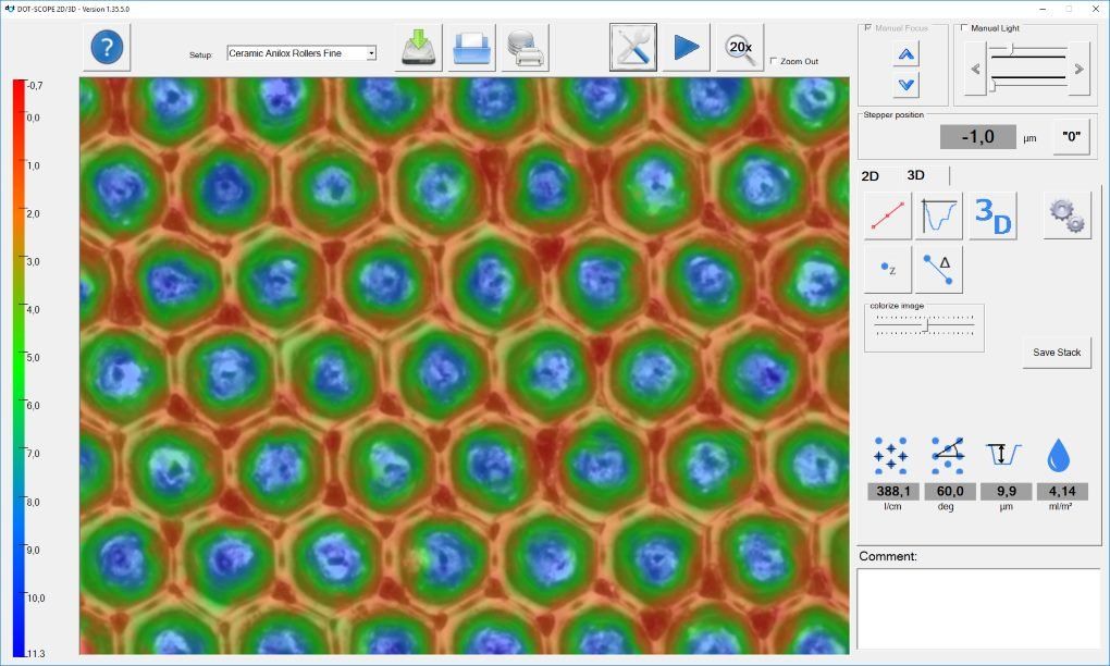
DotScope application view after 3D measurement
Easy operation
The DotScope software is clearly structured and shows a large video image that is easy to see even from a distance. Configurations are already stored for many applications, which can be selected directly from the main program window. Thus, the setting of specific measurement parameters can generally be dispensed with. These configurations exist for example for
- Ceramic anilox rollers
- Chrome anilox rollers
- Laser engraved gravure cylinders
- Graver-engraved gravure cylinder
- flexographic printing plates
- Special screens, such as hatches
Other configurations can easily be saved permanently and easily called up again.
This means that the DotScope is intuitive and can also be operated by newcomers without a great deal of training.
Efficient work
Manually focus the surface and click the record button.
The lighting is set automatically, the images are taken and then the 3D model is determined.
A 3D measurement usually takes between 15...20 seconds.
A serial measurement can also be started in the 3D area. This is interesting if, for example, you want to take several measurements on an anilox roller and then process them together.
When the 3D model is created, the grid, grid angle, suction volume and profile depth are automatically determined. The displayed image can be seamlessly switched from the deep-focus natural view to the pure elevation map. The depth-of-field image can be used, for example, for the analysis of deviating cell shapes or the analysis of stylus fractures.
Profile sections of a line that can be positioned as desired can be generated. Measurement tools for height, width and angle are then available within this profile section.
Furthermore, almost any number of measuring tools for the selective depth, the transverse diagonal, the longitudinal diagonal or web widths can be stored within the elevation map.
A 3D view of the measurement can be generated, which can be rotated and tilted with the mouse. Optionally, spot lighting can also be switched on to make the smallest differences in height clearly visible.
Measurements can be saved and reloaded later for further processing.
The measurement data is saved in the proprietary file formats .m2d and .m3d. In addition, a .jpg of the measurement is generated and the 3d data is stored in the open .x3p format. This means that the recorded data can also be processed with other applications. The 2D functions such as the measurement of longitudinal diagonals, transverse diagonals or web widths are also available.
Perfect data preparation for your everyday production.
After the measurement, the data can be further processed. To do this, the data dialog is opened:
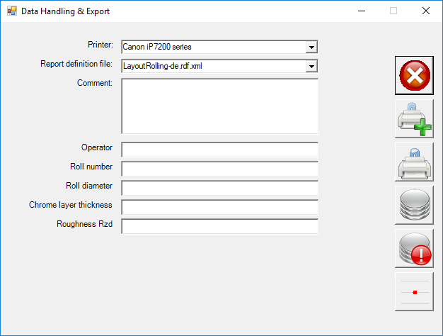
The designations of the input fields can be changed, input fields can be deleted or supplemented. The data dialog offers the option of displaying one or more measurements in a measurement log. A variety of designs are included, e.g
- for single or consecutive measurements
- for anilox rollers with nominal and measurement data
- for comparison before and after cleaning
- for flexographic printing plates
- for several measuring points on an anilox roller
Database connection and quality monitoring of your anilox rollers
- The input and measurement data can also be transferred to an external database using the hotfolder method or written directly to a local database. The latter is ideal for cylinder users who want to monitor the wear or contamination of their cylinders. Previous volume measurements of a cylinder are visualized immediately and can also be presented in tabular form.
Technical requirements:
- Windows 7 or 10
- 2 free USB-A ports, USB2.0 compatible
- 4 GB RAM, recommended at least 8 GB
- Screen resolution min. 1024x720
- Intel / AMD x64 processor with at least 2 cores >= 2 GHz
- recommended Intel Core i5 newer generation, e.g. i5-8265U or i5-8500
- Hard disk with at least 1 GB of free storage space, SSD recommended